3D
The duct damper is considered one of the industrial dampers and is used to control the airflow rate in ducts and diffusers. Moreover, it is used both to disconnect and connect and to control the amount of airflow which is done by the built-in blade. This airflow control becomes important when there is a need for ventilation in one area or in one season of the year, as well as to control the speed and adjust the proper ventilation in different branches of the duct.
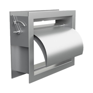
Duct dampers are a device to stop or adjust the airflow in the ducts. The damper may be placed on the main line of the air duct, or it may be placed on any sub-line of the duct damper to block the air entering the room that is unused or to adjust the air entering (hot or cold air) to each room. Duct dampers are adjusted in two ways, manual and automatic. Manual dampers are modified by the damper handle that is installed on the outer space of the damper.
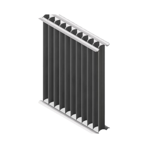
Additionally, these kinds of dampers are available with single-layer blades with V-shaped geometry or double-layer blades with airfoil geometry. In addition, for better air sealing, if required by the customer, a steel air sealing strip is used on the connecting point of the blade shaft to the frame. It is also possible to add a silicone rubber air sealing strip on the edge of the blade to minimize air leakage when the damper is fully closed. Manual duct dampers can be produced in two forms: An opposed blade for more control over the flow and a parallel blade to cut off the airflow more quickly.
The duct damper is divided into two types, like blast valves and dampers:
Making a manual damper
Manual dampers are made as single blades. The blades of this type of damper with the help of a lever made of PVC or iron have the ability to open or close up to a phase difference of 90 degrees. As a result of this change in the angle of the blade in the air path of the duct, the flow path is blocked or reversed and thus the flow is controlled.
Installation conditions: These types of dampers are usually installed flange to flange between two ducts. The standard of damper depth or the empty distance between two ducts for damper installation is 16 cm. If the size of the damper is large, supports taken from the ceiling or wall should be used to restrain it. In addition, these dampers can be installed as a flange head on the end space of the duct or on the openings. For this work, a frame or sub-frame is installed on the opening, and bearing the weight of the damper is needed.
Testing ability: It is possible to measure the amount of leakage based on D500 and AMCA 511-10 standards in the laboratory of Shahrokhi Technical Institute. It is also possible to measure the pressure drop applied in the ducting system by this type of damper and to measure the airflow rate in this type of damper based on the national standards ISIRI 7693 and ISIRI 7695 and the international standards ISO5219 and ISO5221 in the laboratory of Shahrokhi Technical Institute. Balancing the air conditioning system after installing the dampers is another capability of Shahrokhi Technical Institute laboratory.
Finishing: Degreasing is possible through washing in a suds and perk tub for the frame and blade of this type of damper and parallel manual duct damper. It is also possible to paint according to the customer’s instructions. Epoxy, polyurethane and powder colors are applicable for this type of damper.
- Dimensional limit of minimum 25x25 cm and maximum 60x60 cm
- Only galvanized iron, aluminum, carbon steel and steel can be used in making this type of damper.